


A friend once asked me how he could draw a mesh on a line using Unity, or, in other words, create his custom line renderer. This post is about that.
I will start showing how to create and use a spline to represent our line and then I will show how to create a mesh following its curves.
Defining a spline
A spline is a curve defined by control points. There exist several different types of splines in the literature, but for this post I’m going to use the so-called Catmull-Rom spline. I opted by using Catmull-Rom mainly because it’s easier to control since the curve pass through the control points and it’s easy to compute.
You can check a Catmull-Rom explanation here, but in the end we only need the following function to get a point on the curve:
Vector3 GetPointOnSpline(float t, Vector3 p0, Vector3 p1, Vector3 p2, Vector3 p3)
{
	return 0.5f * ((2 * p1) +
			(-p0 + p2) * t +
			(2 * p0 - 5 * p1 + 4 * p2 - p3) * t * t +
			(-p0 + 3 * p1- 3 * p2 + p3) * t * t * t);
}
Where p0, p1, p2 and p3 are four control points and t ([0,1]) is the location of the point to be computed. We can note two things here:
- The point is computed between p1 and p2, i.e., p0 and p3 are only used to help computing the curve.
- We need at least four points to create a curve.
You can create a spline using only linear interpolations. A simple interpolation between two points
Vector3.Lerp(p1, p2, t);is considered a linear curve. If you interpolate two linear curvesVector3.Lerp(Vector3.Lerp(p1, p2, t), Vector3.Lerp(p2, p3, t), t);you have a quadratic curve. Well, my friend, you can interpolate as many interpolations you want. The interpolation of two quadratic curves will give you a cubic curveVector3.Lerp(Vector3.Lerp(Vector3.Lerp(p1, p2, t), Vector3.Lerp(p2, p3, t), t), Vector3.Lerp(Vector3.Lerp(p2, p3, t), Vector3.Lerp(p3, p4, t), t), t);. Those are the famous linear, quadratic and cubic Bèzier curves.
Drawing the spline
Before starting our line renderer, it would be nice to see if the spline computation is working and also to have a preview of the curve to be rendered. However, we cannot just plot the curve on the screen. Since we are only able to draw lines, we actually need to approximate the curve by drawing several lines on it. The more subdivided is the curve, the better will be its representation.
Let’s start by declaring some variables to define the shape of our spline: an array of control points m_ControlPoints and a step size value m_StepSize. We are then going to create intermediate points on the spline with the distance of a step size between them.
Like said in the previous section, a location between two points can be retrieved with a t value between 0 and 1. Each existing spline between two points will range from 0 to 1. In other words, for six control points (cp[0], …, cp[5]), for example, we will have three splines (cp[1] -> cp[2], cp[2] -> cp[3], cp[3] -> cp[4]) each of them ranging from 0 to 1 and a “total t” with lenght of 3.
Be aware that, despite being separated by the same step size, the points are not separated by the same distance.
Then, the way the intermediate points are computed is the following:
- Initialize “local t” and “global t” with 0, and the “total t” with the number of control points minus one.
- Get the four initial control points (cp[0], cp[1], cp[2], cp[3]).
- Compute intermediate point with “local t” and increase “local t” with a step size.
- If “local t” is greater than 1, subtract 1 from “local t”, increment “global t” by one and update the four points for the next four consecutive control points.
- If “global t” is smaller than “total t”, return to (3).
- Compute last intermediate point (which is actually at cp[cp.Length - 1]).
And this is the code:
public void GenerateIntermediatePoints()
{
	if(m_ControlPoints != null && m_ControlPoints.Length >= 4 && m_StepSize > 0.0f)
	{
		float localT = 0f;
		float globalT = 0f;
		float totalT = m_ControlPoints.Length - 3;
		int pointId = 3;

		Vector3 p0 = m_ControlPoints[0].position;
		Vector3 p1 = m_ControlPoints[1].position;
		Vector3 p2 = m_ControlPoints[2].position;
		Vector3 p3 = m_ControlPoints[3].position;

		do
		{
			_IntermediatePoints.Add(GetPointOnSpline(localT, p0, p1, p2, p3));
			localT+=m_StepSize;

			if(localT >= 1f)
			{
				globalT += 1f;
				localT = localT - 1;
				if(pointId  < m_ControlPoints.Length - 1)
				{
					pointId++;
					p0 = p1;
					p1 = p2;
					p2 = p3;
					p3 = m_ControlPoints[pointId].position;
				}
			}
		} while(globalT < totalT);

		_IntermediatePoints.Add(GetPointOnSpline(1, p0, p1, p2, p3));
	}
}
Rendering the line
Now we have all we need to create our line renderer. The objective here is simple, for each interval of two consecutive intermediate points (a segment), we are going to create two triangles forming a quad. The orientation of these quads will be determined by the orientation of the segment and a normal user-defined. We will need also a new variable m_LineWidth that defines… the line width.
We start by taking the two first intermediate points (ip[0] and ip[1]) and computing the segment direction between them (ip[1] - ip[0]). With the segment direction and the user-defined normal, we are able to compute the perpendicular direction that will help us to position the four vertices needed to create our quad.
To compute that perpendicular vector, we only need to do a Cross(segmentDirection, normalDirection). That’s it, the cross product gives us a vector perpendicular to the plane formed by the other two vectors provided.
Remember that Unity uses left-hand coordinates, i.e., the cross product follows the left-hand rule.
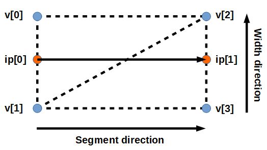
Let’s call this new direction as width direction. Now, with both width direction and segment direction we are able to compute the vertices and define the two triangles of this segment. The vertices are computed as follows:
- v[0] = ip[0] + widthDirection * 0.5.
- v[1] = ip[0] - widthDirection * 0.5.
- v[2] = ip[1] + widthDirection * 0.5.
- v[3] = ip[1] - widthDirection * 0.5.
And then we can define our triangles as (v[0], v[2], v[1]) and (v[1], v[2], v[3]) (clockwise order to render properly (if Unity had right-hand coordinates, it would be counter-clockwise)). The following image shows everybody in their places:
For the following segments, we only need to compute the vertices at the end of the segment since the two vertices first vertices are the same as the last two from the previous segment. The code to create a segment is the following:
void CreateMeshSegment(Vector3 previousPoint, Vector3 currentPoint)
{
	int idTop, idBottom;
	Vector3 segmentDirection = currentPoint - previousPoint;

	Vector3 normal = m_CustomNormal;
	Vector3 widthDirection = Vector3.Cross(segmentDirection.normalized, normal);
	Vector3 halfWidthVector = widthDirection.normalized * m_LineWidth * 0.5f;

	if(_Vertices.Count < 2)
	{
		_Vertices.Add(previousPoint + halfWidthVector);
		_Vertices.Add(previousPoint - halfWidthVector);
	}

	idTop = _Vertices.Count - 2;
	idBottom = _Vertices.Count - 1;

	_Vertices.Add(currentPoint + halfWidthVector);
	_Vertices.Add(currentPoint - halfWidthVector);

	AddQuad(idTop, idBottom, _Vertices.Count - 2, _Vertices.Count - 1);
}

void AddQuad(int id1, int id2, int id3, int id4)
{
	AddTriangle(id1, id3, id2);
	AddTriangle(id2, id3, id4);
}

void AddTriangle(int id1, int id2, int id3)
{
	_Triangles.Add(id1);
	_Triangles.Add(id2);
	_Triangles.Add(id3);
}
Once all the vertices are defined, we need to create our mesh on Unity. The procedure is: instantiate a Mesh, set the vertices, set the triangles, recalculate the bounds, recalculate the normals. Finally, add a MeshFilter, set the Mesh to it and then add a MeshRenderer.
Improving some stuff
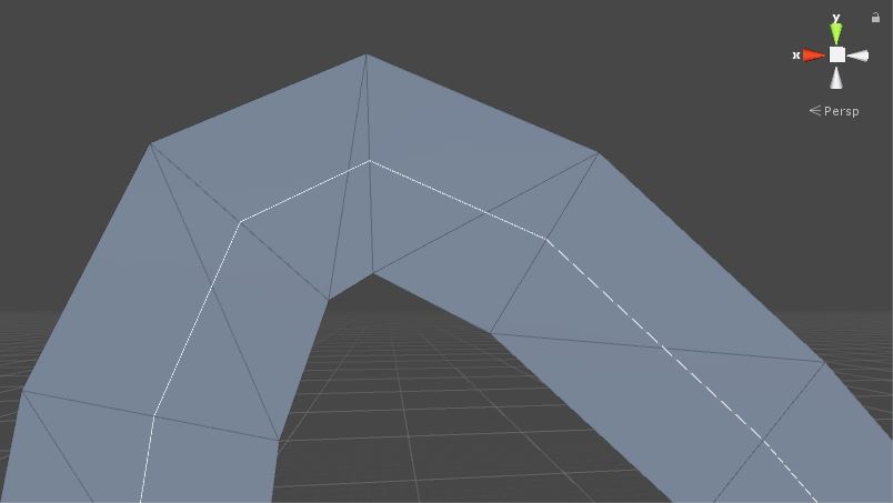
The result is already okay-ish, but it can be improved. The intermediate vertices are oriented according to the previous segment direction and it does not look good, specially when the curve is very tight (check the following image).
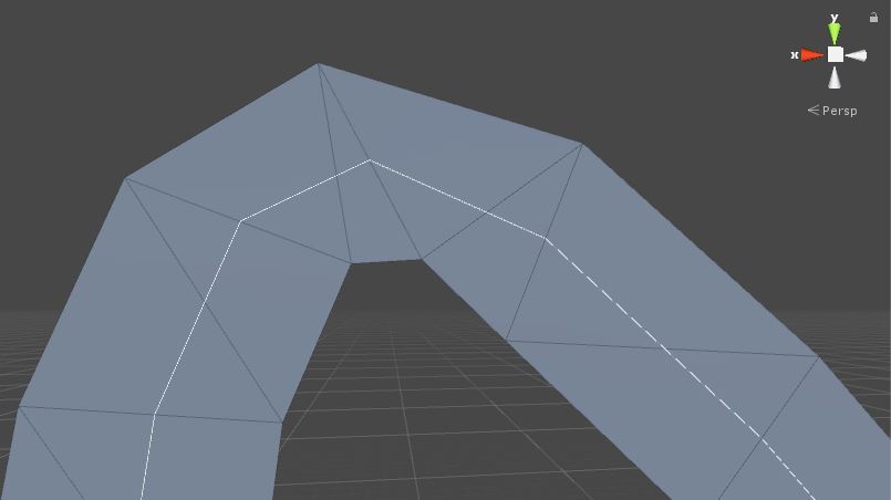
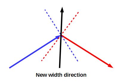
What we can do to improve this is to adjust the vertices in the corner considering the previous and next segments. We do the following:
- Compute the two first vertices of the next segment according to that segment direction.
- Compute the position in the middle of the old and the new vertices on top.
- Compute the position in the middle of the old and the new vertices on bottom.
- Compute the direction formed by those new vertices.
- Adjust the distance between those new vertices to comply with the width distance.
This is the code:
Vector3 halfWidthVector = widthDirection.normalized * _LineWidth * 0.5f;
Vector3 newVertexTop = previousPoint + halfWidthVector;
Vector3 newVertexBottom = previousPoint - halfWidthVector;

Vector3	vertexTop = _Vertices[idTop];
Vector3	vertexBottom = _Vertices[idBottom];

Vector3 midPointTop = vertexTop + (newVertexTop - vertexTop) * 0.5f;
Vector3 midPointBottom = vertexBottom + (newVertexBottom - vertexBottom) * 0.5f;
Vector3 midDirection = (midPointTop - midPointBottom).normalized;

_Vertices[idTop]    = previousPoint + midDirection * _LineHalfWidth;
_Vertices[idBottom] = previousPoint - midDirection * _LineHalfWidth;
Another nice addition we can do is to make the line mesh face the camera. To do so, we only need to use the direction from the segment origin pointing to the camera to compute the width direction. The new width direction can then be computed as follows:
Vector3 normal = m_CustomNormal;
if(m_FaceCamera)
{
	normal = (_CameraPosition - previousPoint).normalized;
}
Vector3 widthDirection = Vector3.Cross(segmentDirection.normalized, normal);
Vector3 halfWidthVector = widthDirection.normalized * _LineHalfWidth;
The end
That’s it, folks! This is just a starting point for creating a line renderer in Unity and it can be improved in several ways. You can find the complete code here. I hope you have enjoyed! See ya!